
News
Measuring Phase Noise of Pulsed RF Signals using the APPH Signal Source Analyzer
In pulsed radar systems, the phase noise of the receiver local oscillator sets the minimum signal level that must be returned from a target in order to be detectable. Since the overall dynamic range of the radar system is influenced by the noise of the transmitted signal, it is not only important to know the absolute noise of the individual oscillators but to know the residual or additive noise of the signal processing devices like power amplifiers and pulse modulators. Because the final signal in most radar systems is pulsed, making absolute phase noise measurements on the pulsed carrier is essential to determining the overall performance of the system.
This application note discusses the various trade-offs in a phase noise measurement of a pulsed RF signal and how easy it can be performed using the APPH signal source analyzer.
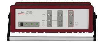
5 MHz to 26 GHz Signal Source Analyzer APPH20G
Performing the Measurement on an APPH signal source analyzer
With the APPH, phase noise of pulsed signals can be analyzed straightforward with pulse repetition frequencies up to several MHz, with narrow pulses below 100 ns, or even with time varying pulse width. Measuring noise on pulsed carrier will be complicated by the following effects:
· Reduced dynamic range due to reduced signal power (duty cycle)
· Limited frequency offset range (PRF/2)
· Saturation of IF stages due to PRF feed through
The specialized architecture of the APPH can mostly overcome the limiting factors and allows performing even very demanding measurement tasks. When connecting with an APPH that supports option PULSED, the GUI will give you the option to activate its pulsed capabilities, allowing measurements of pulsed RF signals as shown in follow picture.
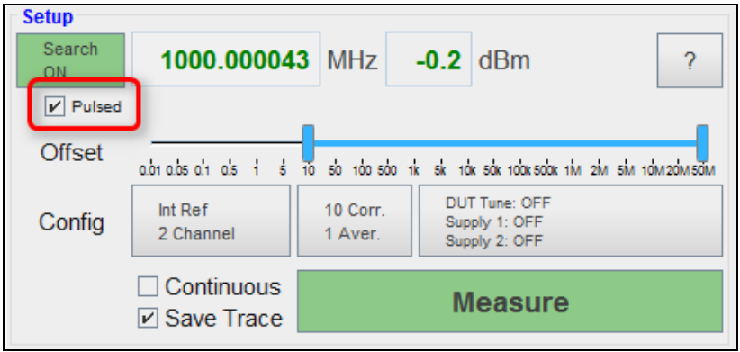
Next, the system needs to know the carrier frequency in order to select the correct internal paths. The automatic detection of the carrier frequency and power level may not always work especially for narrow modulation pulses. In order to tell the GUI the signal parameters, there are two options:
- If possible, switching off the pulse modulation on the RF carrier (i.e. configuring CW only) will allow the unit to detect the signal. When activating the pulse modulation again, the last properly detected frequency will be memorized by the APPH.
- If switching off the pulse modulation is not possible, the carrier frequency must be set manually by deactivating the signal search. Click on the green Search ON button to turn it off. The button will turn red. Now the exact frequency can be entered into the text field.
The measurement can be started by pressing the green Measure button. Upon start, the unit will automatically detect pulse repetition rate (PRF) and duty cycle (i.e. pulse width) and perform the locking process and final measurement autonomously. Depending on the signal and pulse configuration the locking process might take a few seconds. The resulting phase noise will be displayed up to the detected pulse rate to help interpret the measurement. As highlighted in the section before, according to sampling theory, the valid measurement offset range is limited to PRF/2 (because a pulsed RF signal is essentially a sampled version of the CW carrier with sampling rate equal to the PRF).
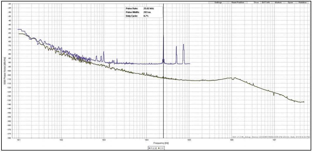
Example measurement of a 10 GHz signal in both CW and pulsed mode.
The resulting phase noise plot for an example measurement can be seen in above picture. It shows the absolute phase noise of a 10 GHz signal.
The measurement was performed for both, CW (in black) and the pulsed carrier (in blue). The pulse modulation was configured with a pulse rate of 25 kHz and a pulse width of 0.3 ms, resulting in a duty cycle of 0.7%. As expected from our previous analysis, for small offsets up to a few hundred Hz, the phase noise of the pulse carrier does not deviate from the CW carrier phase noise. At higher frequency offsets however, the resulting phase noise of the pulsed signal is substantially degraded.
Source: RSI
Others
- TECOTEC GROUP ATTENDED SHIMADZU’S SERVICE MANAGER MEETING IN 2022
- TECOTEC HANDED OVER EDX-7000 X-RAY FLOURESCENCE SPECTROMETER AT NIDEC CHAUN CHOUNG VIETNAM
- INSTALLATION OF CHIP PROCESSING SYSTEM – LANNER/ GERMANY
- TECOTEC completed installation of EDX-LE Energy dispersive X-ray Fluorescence spectrometer at DYT Vina
- TECOTEC DELIVERED AND INSTALLED THE 2ND X-RAY FLUORESCENCE SPECTROMETER - EDX-LE PLUS AT TABUCHI
- TECOTEC Group has handed over PDA-7000 Optical Emissions Spectrometers for Nihon Plast Vietnam
- Bowman XRF Coating Measurement System For Electroless Nickel Plating
- TECOTEC DELIVERED AND INSTALLED SMX-2000 SYSTEM TO NIDEC TECHNO MOTOR VIETNAM