
News
8 Hints for Making Better Measurements Using Analog RF Signal Generators (Part 1)
Signal sources provide precise, highly stable test signals for a variety of component and system test applications. Signal generators add precision modulation capabilities, and are used to simulate system signals for receiver performance testing.
This Keysight Technologies, Inc. guide helps you improve the accuracy of your measurements that involve using RF analog signal sources. You may increase the accuracy of your data by using more than one of the hints in your test setup.
- HINT 1. Improve Source’s Effective Harmonic Distortion.
Use a low pass filter at the output of your source to decrease its harmonic distortion.
- HINT 2. Increase Power Level Accuracy
Use a power meter to increase the accuracy of the signal level at your device under test (DUT).
- HINT 3. Improve Frequency Accuracy
Select the appropriate frequency reference to improve absolute or relative frequency accuracy
- HINT 4. Improve Source Match
Use a fixed attenuator to reduce the mismatch error
- HINT 5. Combine Source Outputs for TOI Measurements
Use a proper setup to isolate sources, improve match.
- HINT 6. Improve FM Deviation Accuracy
Use the Bessel Null method to set your signal generator’s frequency deviation
- HINT 7. Extend the Amplitude Range
Use an amplifier or an attenuator to increase or decrease respectively, the amplitude range of your signal source.
- HINT 8. Select the Optimum Phase Noise Profile
Choose the appropriate phase noise profile to optimize in-channel or out-of-channel measurements.
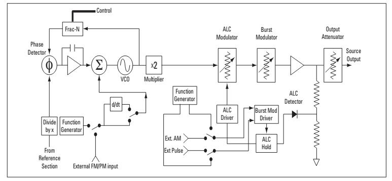
Typical Signal Generator Block Diagram
HINT 1. Improve source’s effective harmonic distortion
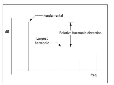
Accurate harmonic distortion measurements require a spectrally pure signal source and a spectrum analyzer. The harmonic distortion of the signal source and the dynamic range of the spectrum analyzer limit the quality of the measurement. However, the signal source is often the limiting factor, with harmonic distortion performance on the order of 30 dB below the fundamental. Figure 1 shows a harmonic distortion measurement. The harmonic distortion of a signal is often specified by stating the amplitude of the largest harmonic in dB relative to the fundamental.
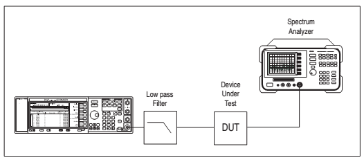
Use a low pass filter to improve the source's effective harmonic distortion, as shown in Figure 2. Choose the cutoff frequency of the low pass filter such that the fundamental frequency is passed largely intact, while the harmonics are attenuated significantly. You can verify the performance of the source/filter combination directly with the spectrum analyzer.
If the loss through the filter at the fundamental frequency is significant, the loss should be accounted for when setting the source output level. Use the spectrum analyzer to check the fundamental level at the output of the filter, or for better level accuracy see Hint 2.
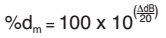
Note:You can calculate the percent distortion for a particular harmonic, mth harmonic as,
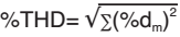
Or you can calculate total harmonic distortion: calculate the distortion for each harmonic as above and find the root sum of the squares,
Source: RSI
Others
- TECOTEC GROUP ATTENDED SHIMADZU’S SERVICE MANAGER MEETING IN 2022
- TECOTEC HANDED OVER EDX-7000 X-RAY FLOURESCENCE SPECTROMETER AT NIDEC CHAUN CHOUNG VIETNAM
- INSTALLATION OF CHIP PROCESSING SYSTEM – LANNER/ GERMANY
- TECOTEC completed installation of EDX-LE Energy dispersive X-ray Fluorescence spectrometer at DYT Vina
- TECOTEC DELIVERED AND INSTALLED THE 2ND X-RAY FLUORESCENCE SPECTROMETER - EDX-LE PLUS AT TABUCHI
- TECOTEC Group has handed over PDA-7000 Optical Emissions Spectrometers for Nihon Plast Vietnam
- Bowman XRF Coating Measurement System For Electroless Nickel Plating
- TECOTEC DELIVERED AND INSTALLED SMX-2000 SYSTEM TO NIDEC TECHNO MOTOR VIETNAM