
News
EARTH RESISTANCE MEASURE AND SOIL RESISTIVITY TEST WITH GEOHM 5
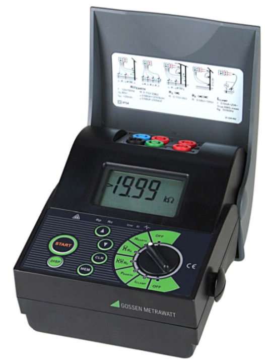
The Geohm 5 earth resistance meter is a hand-held device that uses a dedicated battery power supply for earth resistance measurements. The device is a product of Gossen Metrawatt Germany. Geohm 5 is able to measure Earth resistance and soil resistivity in a variety of ways. Earth resistance measurements comply with the international standard IEC 60364-6-61 and the European standard EN 61.557-5.
Specification:
- Earth resistance measurement range: 0.11Ω - 1.99kΩ
- Earth resistance measurement accuracy: ± (2% of reading + 3 digits)
- Function of measuring effective current: 0 - 19.9A
- Memory stores up to 1000 measured values
- Power supply: 6V (4 AA 1.5V batteries) or 4.8V with rechargeable battery.
The electronic components in the earth resistance measuring device are manufactured using SMD technology (using the paste-type electronic components), ensuring that the device has almost no problems. A LCD monitor makes it easy to view measurement results as well as related parameters
Earth resistance methods of Geohm 5
Earth resistance methods of Geohm 5:
1. Measurement with 4 wires:
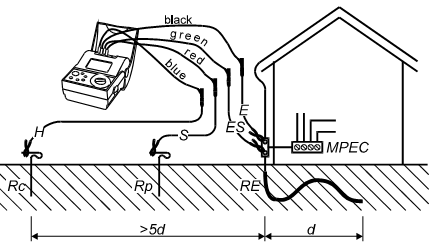
Although using 4 wires to measure, the principle of operation of this method is basically similar to the standard 3-wire earth resistance measurement method. This method requires the use of three-electrode poles to measure the earth resistance, including one main RE pole to be measured and the other two electrically independent piles. Two auxiliary piles are often referred to as RP (Potential) and RC (Current). These two poles may be of inferior quality but must be electrically independent from the main electrode pile.
The principle of measuring soil resistance of this method can be understood as follows. Geohm 5 will provide a current through the grounding system of the required magnitude (current source) and the current through the extra RC (Current) will be measured. The voltage drop between the test piles RE and the second auxiliary RP (Potential) were measured.
The potential difference between the RP pile and the RE pile is measured by voltmeter, and the current flowing between the RC pile and the RE pile is measured by ammeter. According to Ohm's law V = IR deduce R = V / I, we have the resistance of the ground pole.
2. Measurement with current clamp:
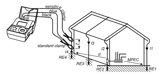
This is the only method that helps you measure earth resistance without an earthing system. The method is done by clamping the current clamp via the main ground wire.
The principle of this method is to place 2 current clamps around the earthing wire. One clamp is fed into the earthing loop with a known signal. The other clamp will measure the current flowing in the loop. Therefore, for this method to be performed, a ring resistor is required. With more parallel earth lines number, the more measurement value will closer with actual earth resistance value.
3. Soil resistivity test:
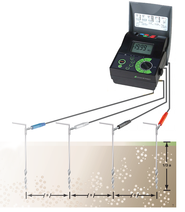
This method uses four small earthing poles, which are equidistant from each other at least 3 times the depth of the pile and must lie on a straight line.
Resistivity is often affected by interfering sources such as metal fragments in the soil, so changing the position and depth of piles to get more data is always suggested.
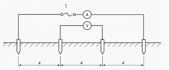
The formula for calculating the resistivity is as follows:
p = 2πaR
p: Soil resistivity.
a : The distance between the piles
R : The soil resistance between piles, calculated by the formula R = V / I and measured according to the diagram below
Source: TMC
Others
- TECOTEC GROUP ATTENDED SHIMADZU’S SERVICE MANAGER MEETING IN 2022
- TECOTEC HANDED OVER EDX-7000 X-RAY FLOURESCENCE SPECTROMETER AT NIDEC CHAUN CHOUNG VIETNAM
- INSTALLATION OF CHIP PROCESSING SYSTEM – LANNER/ GERMANY
- TECOTEC completed installation of EDX-LE Energy dispersive X-ray Fluorescence spectrometer at DYT Vina
- TECOTEC DELIVERED AND INSTALLED THE 2ND X-RAY FLUORESCENCE SPECTROMETER - EDX-LE PLUS AT TABUCHI
- TECOTEC Group has handed over PDA-7000 Optical Emissions Spectrometers for Nihon Plast Vietnam
- Bowman XRF Coating Measurement System For Electroless Nickel Plating
- TECOTEC DELIVERED AND INSTALLED SMX-2000 SYSTEM TO NIDEC TECHNO MOTOR VIETNAM