
News
HOW TO MAKE A GREAT OSCILLOSCOPE MEASUREMENT (PART 2)
In oscilloscopes today, making a good signal measurement is easy. However, making a great measurement takes some expertise. As edge speeds increase and voltages decrease, your signal’s margin of error becomes smaller and smaller. Digital oscilloscopes have turned manual measurements into an automated process, allowing you to make adequate measurements quickly and easily. However, turning that good measurement into a great measurement requires a little extra knowledge and effort. Following some key best practices will give you much higher accuracy and confidence in your measurements. Signal scaling and bits of resolution will impact the quality of your measurement, so it’s crucial to understand how to get the most out of your oscilloscope.
Bits of Resolution
Bits of resolution describes the precision of an analog-to-digital converter (ADC). The higher the bits of resolution, the more vertical quantization levels an ADC can identify when sampling an analog signal.
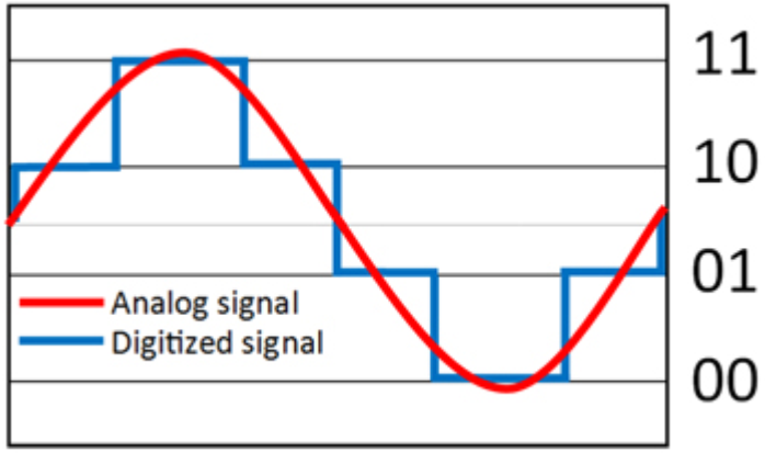
For example, Figure 5 shows a two-bit ADC. The analog-signal input is in red, and the quantized digital-signal output from the ADC is in blue. A two-bit ADC has four vertical quantization levels. So, the analog signal will be quantized down to one of four values.
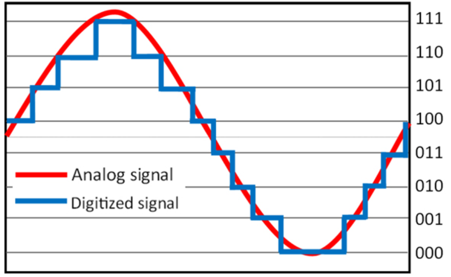
In a three-bit ADC (Fig. 6), we see that there are eight possible levels for the digital signal. This significantly increases the precision of the ADC, and the analog signal will be more accurately represented.
Most oscilloscopes have eight bits of resolution; the signal viewing area of the oscilloscope’s screen represents eight bits. A digital oscilloscope uses the quantized waveform to make measurements. So, the more accurately ADC portrays the analog signal, the more accurate the measurements. Looking back at Figure 3, we see that by not scaling the signal to the full vertical height of the screen, we aren’t taking advantage of all of the oscilloscope’s bits of resolution. When we scaled the signal to maximize use of the oscilloscope’s resolution (Fig. 4, again), we were able to make a better VPP measurement.
This has important ramifications, especially if you’re using more than one channel at a time. For example, it’s common to make power measurements using two channels (current and voltage). To make a great power measurement, you must scale both signals to the full height of the oscilloscope’s screen instead of stacking them above each other on the screen. If you only use half of the screen for voltage and the other half for current, the oscilloscope can’t use all bits of resolution on each waveform.
It is important to note, however, that the oscilloscope’s bits of resolution are just one part of the system, and the entire signal path must be observed to consider the total effective number of bits. This includes external factors such as probing and system noise, as well as internal factors such as your oscilloscope’s noise floor. If the system’s noise is high enough, an increased number of bits of resolution will only show noise.
Conclusion
Knowing how to best use your oscilloscope is crucial if you want to move from making good measurements to making great measurements. More accurate measurements further boost confidence in verifying and debugging designs. Understanding how to scale your signals properly to take full advantage of sample rate and bits of resolution is a crucial skill for success while testing and debugging.
Source: RSI
Others
- TECOTEC GROUP ATTENDED SHIMADZU’S SERVICE MANAGER MEETING IN 2022
- TECOTEC HANDED OVER EDX-7000 X-RAY FLOURESCENCE SPECTROMETER AT NIDEC CHAUN CHOUNG VIETNAM
- INSTALLATION OF CHIP PROCESSING SYSTEM – LANNER/ GERMANY
- TECOTEC completed installation of EDX-LE Energy dispersive X-ray Fluorescence spectrometer at DYT Vina
- TECOTEC DELIVERED AND INSTALLED THE 2ND X-RAY FLUORESCENCE SPECTROMETER - EDX-LE PLUS AT TABUCHI
- TECOTEC Group has handed over PDA-7000 Optical Emissions Spectrometers for Nihon Plast Vietnam
- Bowman XRF Coating Measurement System For Electroless Nickel Plating
- TECOTEC DELIVERED AND INSTALLED SMX-2000 SYSTEM TO NIDEC TECHNO MOTOR VIETNAM