
News
How to measure additive phase noise of amplifiers using the APPH (Part 1)
Additive phase noise, also referred to as residual phase noise, is the self phase noise of a component that adds to an existing signal as the signal passes through it. Hence the additive (residual) phase noise measurement is a valuable technique used to identify the phase noise contribution of a single component as part of a system design.
Introduction:
One benefit of the APPH SSA is its capability to measure additive phase noise (also referred to as residual phase noise) of non-self-oscillating DUTs like amplifiers, transmitters, or even mixers or prescalers. This can be done on a single channel or using two-channel cross-correlation to achieve lowest phase noise.
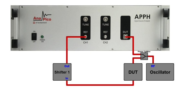
Figure 1: Schematic of the measurement setup
Additive noise measurements are typically at a lower noise level and are more difficult to perform than absolute phase noise measurements, requiring careful measurement setup and calibration. While the setup involves traditional microwave plumbing, the calibration can be tedious and prone to significant error. Anapico’s APPH Series of phase noise analyzers addresses this problem by completely automating the calibration. This application note focuses on the single-channel additive phase noise measurement of an RF amplifier
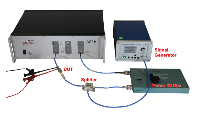
Figure 2: Photograph of the test setup
Theory:
The single channel additive phase noise measurement works as follows as shown in the schematic diagram of Figure 1: A stimulus source is set to the desired frequency. The signal is split into two paths. One path is fed into the DUT input and the other path is fed into the REF input. In one signal path a phase shifter is inserted to allow phase adjustments between REF and DUT port.
The APPH compares the phase of the DUT and REF paths using a low noise phase detector. Using the phase shifter, the two signal paths are set to phase quadrature (90 degrees apart) at the phase detector. It can be shown that under perfect quadrature the correlated noise in the two signal paths (in particular phase noise from the stimulus source) is cancelled out. Without any DUT, this measurement can be used to determine the setup phase noise floor. Adding the DUT into one signal path will add the DUT’s phase noise and will be detected by the phase detector as deviation from quadrature (because it is only appearing in one signal path). Note that in a single channel measurement, the phase shifter and the DUT can be located in either the DUT or REF signal paths. This gives some additional flexibility in the measurement setup.
Measurement setup and procedure:
The actual hardware setup is shown in Figure 2. Besides of the APPH, a low phase noise signal source (in our case we use the APSIN20G signal generator), a power splitter and an electrically tunable or mechanical phase shifter is required.
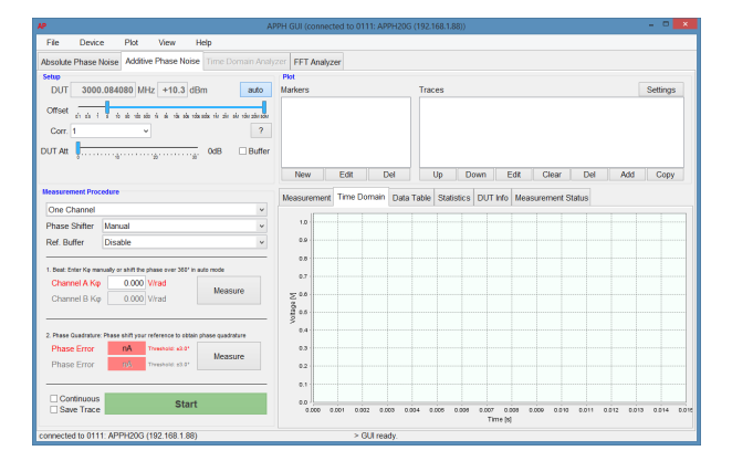
Figure 3: GUI screenshot of the "Additive Phase Noise" tab
The measurement procedure can be split into two steps:
A. Determine the measurement noise floor
B. Perform the actual measurement on DUT
Determining the setup noise floor (step A) is especially important to make sure that the DUT noise is properly defined and not influenced by other noise contributors. This step may be omitted if instrument noise floor is already known for the particular setup. In step B, the DUT is added into one signal path and the measurement is repeated this time including the DUT. Both steps require a full measurement to be performed, the only difference is that the DUT is replaced with a cable to measure the noise floor.
Source: RSI
Others
- TECOTEC GROUP ATTENDED SHIMADZU’S SERVICE MANAGER MEETING IN 2022
- TECOTEC HANDED OVER EDX-7000 X-RAY FLOURESCENCE SPECTROMETER AT NIDEC CHAUN CHOUNG VIETNAM
- INSTALLATION OF CHIP PROCESSING SYSTEM – LANNER/ GERMANY
- TECOTEC completed installation of EDX-LE Energy dispersive X-ray Fluorescence spectrometer at DYT Vina
- TECOTEC DELIVERED AND INSTALLED THE 2ND X-RAY FLUORESCENCE SPECTROMETER - EDX-LE PLUS AT TABUCHI
- TECOTEC Group has handed over PDA-7000 Optical Emissions Spectrometers for Nihon Plast Vietnam
- Bowman XRF Coating Measurement System For Electroless Nickel Plating
- TECOTEC DELIVERED AND INSTALLED SMX-2000 SYSTEM TO NIDEC TECHNO MOTOR VIETNAM