
News
How to measure additive phase noise of amplifiers using the APPH (Part2)
Additive phase noise, also referred to as residual phase noise, is the self phase noise of a component that adds to an existing signal as the signal passes through it. Hence the additive (residual) phase noise measurement is a valuable technique used to identify the phase noise contribution of a single component as part of a system design.
The GUI setup:
Starting the GUI, first the connection to the APPH is established and the “Additive Phase Noise” tab is selected (see Figure 3). The next steps are:
1) As in the absolute phase noise tab, select offset range and number of correlations. Then choose if additional signal attenuation or amplification is desired using the input attenuator / low noise amplifier stage.

Figure 4: Rotating phase at the phase detector using the phase shifter will determine phase detector constant of the measurement setup
NOTE: Care must be taken, that the DUT and the REF ports are operated at appropriate power levels.
The DUT input power should be between +3 and +10 dBm. Above +10 dBm, the DUT input attenuator should be adjusted. Below +3 dBm, the input low noise amplifier may help to improve the measurement noise floor.
The REF input should be operated between +9 and +17 dBm. Below +9 dBm the REF input low noise amplifier may be switched in to improve the noise floor.
It is recommended to adjust the measurement setup if possible before using the buffer or attenuation options. For instance, the DUT can be placed either on the DUT or on the REF side which will effect the power levels at the DUT and RED input.
To measure the input power of the signals, use the DUT input and press the "auto" button to start the frequency and power measurement of the attached signal.
2) Select the “One Channel” measurement. The phase shifter can be chosen to be either a manually controlled phase shifter (as in this example), a voltage controlled phase shifter (via the APPH tuning port), or a remote controlled digital phase shifter from Colby Instruments (Colby compatibility not yet implemented, ask Anapico support for status).
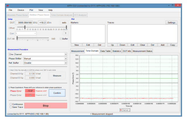
Figure 5: Adjusting to phase quadrature using phase shifter
3) Once the setup is completed, the calibration procedure is started by clicking on the first “Measure” button. Using the phase shifter, the phase is now rotated continuously over 360 degrees to determine the phase detector constant (see Figure 4). Complete the calibration step by clicking on the corresponding "Confirm” button.
4) In a next step, the signals at the phase detector are adjusted to quadrature (90° phase shifted in respect to each other) using the phase shifter (see Figure 5 & Figure 6). Clicking on the second "Measure" button will continuously show the current phase error which has to be reduced to 0° by phase shifting the reference. Once the phase error is minimized, complete the calibration step by clicking on the second “Confirm” button.
5) Once the phase detector has near quadrature phases an is confirmed by the user, the “Start” button is enabled and the actual measurement can be performed (see Error! Reference source not found.) by clicking on the green "Start" button. The GUI will automatically switch to the phase noise plot and show the result after the measurement is finished
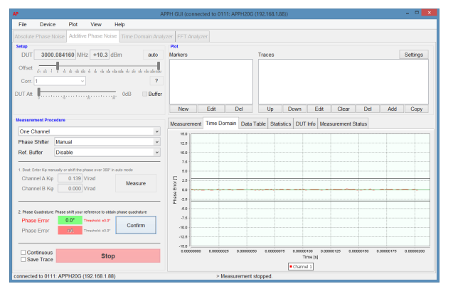
Figure 6: Quadrature achieved within accepted tolerance range
Analyzing the result:
Figure 7 shows the measured instrument noise floor (as measured in step A) of the particular setup as the blue curve. Using a stimulus source of +16 dBm at 2 GHz, the setup noise floor is lower than -175 dBc/Hz for offsets above 10 kHz and below -140 dBc/Hz at 10 Hz offset, allowing. Using two channel cross-correlation, noise floors below -190 dBc/Hz can be achieved.
The measurement including the DUT amplifier is shown as the green curve. For offsets up 4 MHz, the DUT phase noise dominates the setup noise floor (i.e. shows a higher phase noise value), indicating that the measurement is dominated by the DUT noise. At higher offsets, the green trace reaches the setup noise floor. Only a cross-correlation measurement will enable lower level measurements.
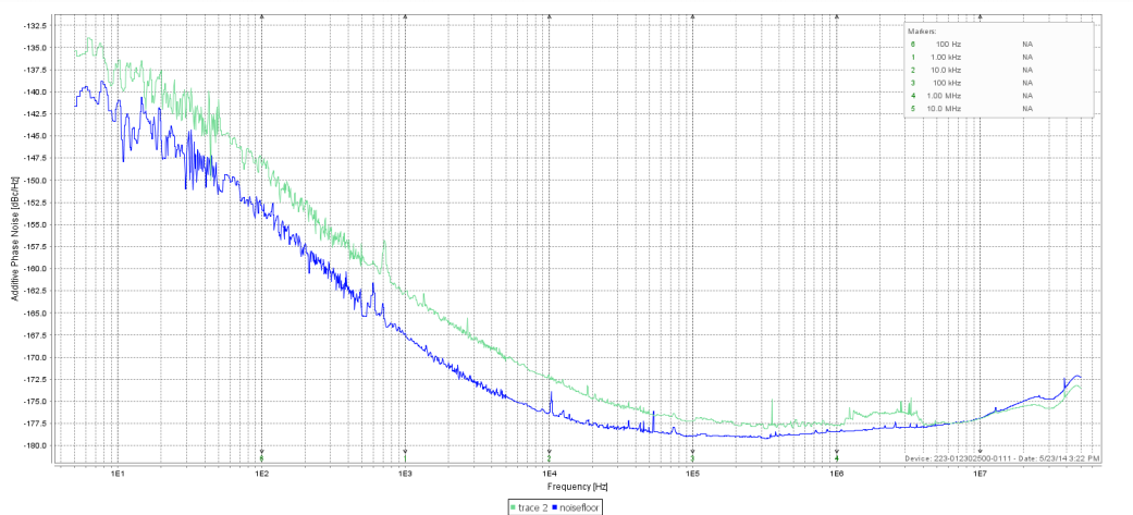
Figure 7: Phase noise of the DUT amplifier
Conclusion:
As shown in this application note, a simple procedure using the APPH allows measurement of amplifier phase noise at very low phase noise levels. For lowest phase noise floors, the setup must be duplicated on a second measurement channel and cross-correlation must be applied.
Source: RSI
Others
- TECOTEC GROUP ATTENDED SHIMADZU’S SERVICE MANAGER MEETING IN 2022
- TECOTEC HANDED OVER EDX-7000 X-RAY FLOURESCENCE SPECTROMETER AT NIDEC CHAUN CHOUNG VIETNAM
- INSTALLATION OF CHIP PROCESSING SYSTEM – LANNER/ GERMANY
- TECOTEC completed installation of EDX-LE Energy dispersive X-ray Fluorescence spectrometer at DYT Vina
- TECOTEC DELIVERED AND INSTALLED THE 2ND X-RAY FLUORESCENCE SPECTROMETER - EDX-LE PLUS AT TABUCHI
- TECOTEC Group has handed over PDA-7000 Optical Emissions Spectrometers for Nihon Plast Vietnam
- Bowman XRF Coating Measurement System For Electroless Nickel Plating
- TECOTEC DELIVERED AND INSTALLED SMX-2000 SYSTEM TO NIDEC TECHNO MOTOR VIETNAM