
News
THE DIFFERENCE BETWEEN GROUND CONTINUITY TEST AND GROUND BOND TEST
In electrical safety testing, you've probably seen the terms "Ground continuity test" and "Ground bond test" in specialized documents. These are two tests that need to be performed when assessing the electrical safety of a device or electrical system. So, what does "Ground continuity test" and "Ground bond test" mean? Let’s find out
Ground continuity test và Ground bond test:
Both of the above tests are related to the inspection of the earthing system of electrical systems as well as of electrical equipment. So, to better understand Ground continuity test and Ground bond test, we also need to understand what is Grounding? And what is bonding?
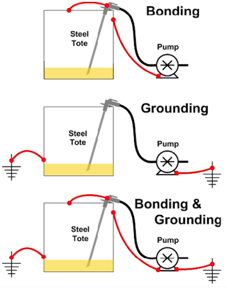
Grounding: Is the direct connection of an object to the earth. We can see, earthing rods, earthing rings, ... will be considered as grounding because they are in direct contact with the ground. A component connected directly to the soil is also called grounding. For example, in the figure on the right, the connection between the pump casing and the steel casing of the container with the soil, is called Grounding.
Bonding: Unlike grounding, bonding is only the connection between the conductive components in the earthing system. For example, the connection between the case and the metal base of the device is called Bonding. Or as shown in the picture, the pump housing and suction nozzle are connected to the steel casing of the container, we call it Bonding together
Ground continuity test and Ground bond test:
That so, the Ground continuity test is to test whether the metal components of the device that can contact users are well connected with the ground wire. This test is performed by a low-current DC signal that runs through its connections and measures its resistance. The result of should have a resistance under 1 ohm.
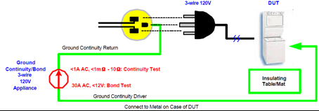
Diagram for Ground continuity test
Ground bond test is a method of testing the connection between the shell components of the equipment and the grounding component, to see if the connection between them is good enough or not. This method uses a signal with a high current (about 25A) on the surface of the device, then measures the voltage drop across the earthing system of the device from which the resistance is measured. This helps to check whether the connection between the case and the grounding of the device allows this high current to flow safely. Because the resulting resistance is usually very small and the resistance of the probe can falsify the results, a kelvin cable (4-wire cable ) is used to measure the electrical support for the test.
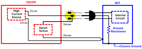
Diagram for Ground bond test
Ground continuity and Ground bond test equipment:
With Ground continuity test, we merely test the continuity of the housing with the ground wire, so just using low resistance meters will be able to meet the requirements.
For Ground bond testing, it is necessary to use a specialized device to perform this test.
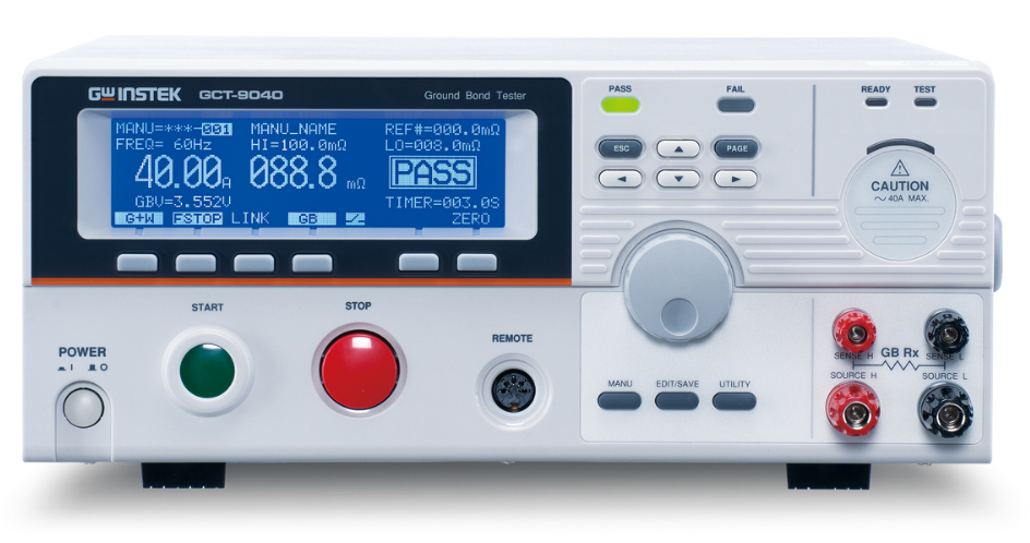
GTC-9040 AC Ground Bond Tester
GTC-9040 AC Ground Bond Tester is a specialized product, used to test and evaluate the connection of the shell components to the grounding part of any electrical equipment (Ground bond test). The device is capable of generating test signals with currents up to 40A AC. The smallest resistance value GTC-9040 can be measured is 1mΩ.
Specification
- Output current: 3A ~ 40A (Resolution 0.01A).
- Test Voltage: Max 8V AC (Frequency 50 / 60Hz).
- Resistance measurement range: 1.0mΩ ~ 650.0mΩ (Resolution 0.1mΩ).
- Measurement time for installation: 0.5s ~ 999.9s.
- Method of measurement: 4-wire resistance measurement.
Source: TMC
Others
- TECOTEC GROUP ATTENDED SHIMADZU’S SERVICE MANAGER MEETING IN 2022
- TECOTEC HANDED OVER EDX-7000 X-RAY FLOURESCENCE SPECTROMETER AT NIDEC CHAUN CHOUNG VIETNAM
- INSTALLATION OF CHIP PROCESSING SYSTEM – LANNER/ GERMANY
- TECOTEC completed installation of EDX-LE Energy dispersive X-ray Fluorescence spectrometer at DYT Vina
- TECOTEC DELIVERED AND INSTALLED THE 2ND X-RAY FLUORESCENCE SPECTROMETER - EDX-LE PLUS AT TABUCHI
- TECOTEC Group has handed over PDA-7000 Optical Emissions Spectrometers for Nihon Plast Vietnam
- Bowman XRF Coating Measurement System For Electroless Nickel Plating
- TECOTEC DELIVERED AND INSTALLED SMX-2000 SYSTEM TO NIDEC TECHNO MOTOR VIETNAM